CURRENT RESEARCH
Last Updated: February 26, 2005
The HTDMA (Humidified Tandem Differential Mobility Analyzer) [Rader and McMurry, 1986] was built to measure the hygroscopicity of aerosols (the uptake of water by aerosols in equilibrium with less than 100% Relative Humidity (RH)).
Using a Cloud Condensation Nuclei Counter (CCNc), we compare the stable growth of aerosols at less than 100% RH with their unstable growth at greater than 100% RH, while simultaneously observing aerosol chemical composition using a Thermal Desorption Chemical Ionization Mass Spectrometer (TDCIMS).

Below is a schematic of the HTDMA system (within the HTDMA box).

S = Sheath Flow
A = Aerosol Flow
The basic description is: the aerosol flow is conditioned in the first humidifier to a chosen RH between 0% and 40% RH, the aerosol particles are charged (by passing through a radioactive source) and then classified at a constant voltage in DMA 1. Then the monodisperse aerosol flow is humidifed further to a chosen RH up to 90% and allowed time to grow in a variable volume dead-space before entering DMA 2, where the voltage is scanned in order to see how much the aerosol particles have grown, using a Condensation Particle Counter (CPC) (TSI-3020, which is similar to the TSI-3022). The aerosol flow is sent through a single-tube nafion dryer before entering the CPC, in order to reduce dilution of butanol and condensation in the lines.
We reserve the option to humidify the inlet aerosol flow, in order to study deliquescence and/or dissolution kinetics.
We also reserve the option to vary the residence time of the aerosol between DMA1 and DMA2, in order to study growth kinetics, which have been hypothesized to slow due to the presence of organic, surface-active films on ambient aerosol particles.

|
There is a temperature sensor (thermistor) and relative humidity sensor located at each labeled point on the aerosol and sheath flows above. The temperature is controlled within the TDMA box (29oC) using a re-circulating blower, blanket heaters and omega temperature controller, as illustrated in the adjacent diagram. In addition, two water impingers (through which filtered, dry air is bubbled in order to generate water vapor saturation) have their own heaters in order to overcome cooling from evaporation. |
PHOTOGRAPHS and DESCRIPTION:
(Click on thumbnail to enlarge. You can drag the enlarged images by dragging the top white bar.)

|
Back view of the HTDMA, showing the Mass Flow Controller (MFC) hookups. Two of the MFCs control the dry and humid air flow to the central humidifier (between the two DMA's), another two MFCs control the humidify at the inlet (upstream of the first DMA) and one additional MFC provides dry air to the nafion dryer at the outlet. |
|
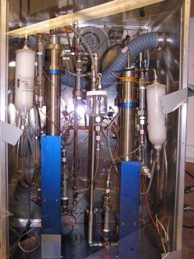
Front view of the HTDMA, inside the HTDMA box. |

|
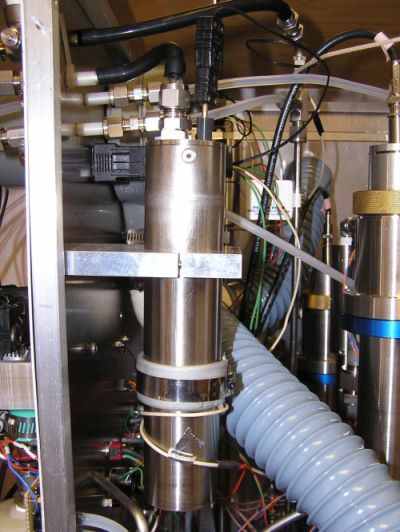
Side view of the HTDMA, which has been opened to reveal the recirculating sheath flow for the second DMA (which recirculates in order to stabilize the relative humidity). The looped tubing provides a measureable pressure drop from which the sheath flow rate can be determined. |

|
Close up view of a humidity and temperature sensor. |
|
Close up view of one of the two impingers (where air bubbles through water and exits at 100% RH). |

|
Close up view of the HTDMA box temperature controller. Two other controllers are used to regulate the temperature of the water in the impingers (since evaporation leads to cooling). |

|
One of the blowers that controls the recirculating sheath flow. |
Citations:
1) Rader, D.J. and P.H. McMurry (1987). "Evaporation Rates of Monodisperse Aerosols in the 0.02 to 0.2 μm Diameter Range", Aerosol Sci. Technol. 6:247−260.